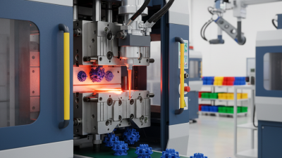
Injection pressure is one of the most misunderstood variables in plastic injection molding. It affects filling speed, packing quality, part weight, dimensional stability, and surface appearance. Yet higher pressure does not automatically produce better parts. It can create flash, excessive stress, burned material, or premature mold wear.
John Bozzelli, a respected injection molding consultant and founder of Scientific Molding, often teaches, “You can’t control what you don’t measure.” That principle guides this practical review of the top 10 injection pressure problems and solutions. A pressure spike on the machine screen may indicate a blocked gate, cold material, poor venting, or an incorrect transfer position. A sudden pressure drop may reveal leakage, inconsistent pellets, or unstable screw recovery.
Small details matter. Watch the pressure curve. Check the actual cushion. Compare part weights across several cycles. Inspect the gate for freeze-off and the mold surface for flash. These actions turn vague defects into measurable evidence.
No checklist is flawless. Even experienced technicians can blame injection pressure too quickly. Sometimes the real cause is melt temperature, moisture, mold temperature, or material variation. That is why reliable troubleshooting requires records, repeatable tests, and careful observation.
This guide focuses on practical decisions rather than simple pressure adjustments. Each problem connects symptoms with likely causes and corrective actions. The goal is not to chase a perfect number. It is to establish a stable process that produces consistent parts, protects equipment, and supports informed engineering decisions.
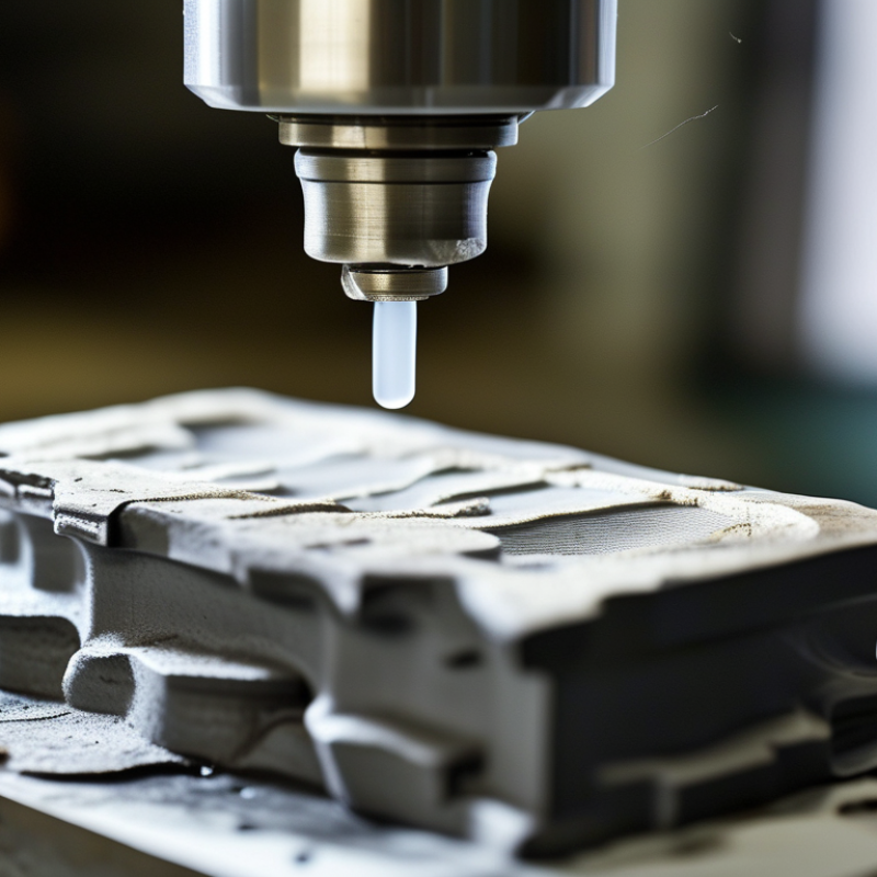
Injection pressure is the force that pushes molten material into a mold cavity. It controls filling speed, packing, surface detail, and part weight. Pressure is not clamp force. High pressure can hide poor venting, restricted gates, or incorrect melt temperature. Low pressure may create short shots, sink marks, weld lines, or weak corners. In production, I check the pressure curve, not only the peak number. The curve shows where resistance rises and filling becomes unstable.
Ten recurring pressure problems include flashing, hesitation, burn marks, voids, warpage, dimensional drift, inconsistent shots, short shots, sink marks, and weld lines. Small changes matter. A rising peak often points to a blocked vent, cold runner, or premature freeze-off. A sudden drop may indicate leakage, feed interruption, or unstable cushion. Measure before adjusting. Confirm material temperature, mold temperature, screw recovery, check-ring sealing, and actual cavity fill time. Change one variable at a time. Reducing pressure can limit flash, but it may worsen incomplete filling or knit-line strength.
A reliable setup uses a pressure limit with a controlled transfer point from filling to packing. Packing pressure and hold time should match gate freeze time, not habit. I once treated a pressure spike as a machine fault; the real cause was a partially blocked vent. That mistake delayed troubleshooting and produced unstable samples. A perfect setting rarely exists. Operators should record pressure, part weight, dimensions, and defects together. This evidence makes each adjustment safer and more repeatable.
| No. | Injection Pressure Problem | Typical Symptoms | Common Causes | Recommended Solutions | Important Checks |
|---|---|---|---|---|---|
| 1 | Injection Pressure Too Low | Short shots, incomplete ribs or bosses, weak weld lines, and inconsistent part weight. | Insufficient injection pressure limit, excessive melt viscosity, restricted gates or runners, or inadequate injection speed. | Increase pressure gradually within the machine and mold limits. Verify melt temperature, injection speed, gate dimensions, and material drying requirements. | Confirm that the pressure limit is reached only near the end of filling and that the screw still has a stable transfer position. |
| 2 | Injection Pressure Too High | Flash, mold-parting-line stress, difficult mold opening, excessive machine load, or dimensional growth. | Overly fast filling, blocked vents, excessive holding pressure, cold material, or an undersized flow path. | Reduce injection or holding pressure in small steps. Improve venting, check the gate and runner system, and confirm that the melt temperature is suitable for the resin. | Monitor peak pressure, clamp-force margin, flash location, and part dimensions after each adjustment. |
| 3 | Pressure Spike During Filling | Sudden pressure increases, machine alarms, burn marks, flash, or unstable cycle-to-cycle pressure. | Air entrapment, a partially blocked gate, sudden flow-front hesitation, cold spots, or abrupt injection-speed changes. | Inspect and clean the gate, improve venting at the final-fill area, smooth the speed profile, and eliminate cold spots in the mold. | Compare the pressure curve with the screw-position curve to identify the exact point where resistance increases. |
| 4 | Pressure Drop in the Melt Delivery System | Longer fill time, underfilled sections, surface defects, and greater variation between cavities. | High pressure loss in the nozzle, sprue, runners, filters, or gates; excessive shear; or insufficient melt temperature. | Check for restrictions and wear, clean the nozzle and filter, balance the runner system, and review gate size and melt temperature. | Measure pressure before and after the suspected restriction and compare cavity fill behavior. |
| 5 | Insufficient Holding Pressure | Sink marks, internal voids, low part weight, poor packing around thick sections, and excessive shrinkage. | Holding pressure is too low or too short, the gate freezes prematurely, or the transfer point occurs too early. | Increase holding pressure or holding time carefully, optimize the transfer position, and verify that the gate remains open long enough for packing. | Use part weight, sink-mark depth, and gate-freeze studies to determine when additional packing no longer improves the part. |
| 6 | Excessive Holding Pressure | Flash, high residual stress, warpage, dimensional oversize, and difficult ejection. | Holding pressure or time is higher than required, the gate remains open too long, or the part is overpacked. | Reduce holding pressure and time incrementally while monitoring weight and dimensions. Confirm that cooling is sufficient before ejection. | Check for stress whitening, birefringence where applicable, warpage direction, and changes in part weight. |
| 7 | Unstable Pressure From Cycle to Cycle | Variable part weight, inconsistent dimensions, random short shots, and changing surface quality. | Irregular plasticizing, fluctuating material moisture, inconsistent cushion, unstable temperature control, or check-ring leakage. | Stabilize material drying and feeding, verify barrel and mold temperatures, inspect the screw check ring, and maintain a consistent cushion. | Trend peak pressure, transfer position, cushion, recovery time, and actual melt temperature over multiple cycles. |
| 8 | Pressure Imbalance in Multi-Cavity Molds | Different cavity weights, uneven filling, cavity-to-cavity flash, and variations in shrinkage or dimensions. | Unbalanced runners or gates, unequal cooling, cavity geometry differences, or variations in venting. | Balance runner and gate dimensions, equalize cooling and venting, and use cavity pressure monitoring when available. | Compare fill time, pressure response, part weight, and dimensions for every cavity rather than relying only on average values. |
| 9 | Pressure Loss Caused by Poor Venting | Burn marks, weld-line weakness, short shots at the end of fill, trapped-air voids, and localized flash. | Vents are blocked, too shallow, incorrectly positioned, or absent near the final filling and air-trap locations. | Clean existing vents and add or modify venting at appropriate locations. Keep vent dimensions suitable for air removal without causing flash. | Inspect the final-fill area, vent land, and parting line; compare defects before and after vent maintenance. |
| 10 | Incorrect Pressure Measurement or Setup | Displayed pressure does not match process behavior, unexplained alarms, or incorrect comparisons between machines. | Confusion between hydraulic pressure and plastic pressure, incorrect pressure-sensor calibration, or inconsistent machine settings. | Identify the pressure measurement location and units, calibrate sensors, document the machine setup, and compare plastic pressure at the same screw position. | Record pressure, screw position, injection speed, transfer point, cushion, melt temperature, and holding-time settings together. |